Challenges
Working with embedded systems comes with different set of challenges unlike a software programming. The challenge start form an early stage of the project choosing which components you should use and their compatibility with the microcontroller; communication protocols, power consumption, sensitivity, package volume and so on. Once that stage is passed you have to deeply understand the component in order to seamlessly work with the MCU and this might require you to even build a separate circuit before the actual connection to the MCU.
Even though, in this project many required circuitry like power regulator, MCU power LED and many more are pre built on the Mega128 PCB module found on figure 4; however, at some point building an external circuit with 100 W resisters was required in addition in order for the encoder module to work correctly.
The challenges will even progress deep in to the MCU programming especially whenever you need to program a routine that does not exist in the provided AVRLibc library. For instance, the encoder wheel was tough to program since it require additional new set of functions which the AVRLibc failed to include therefore, a fresh code was needed to make it work/read the device.
Floating numbers
Due to the fact of ATMega128 MCU design limitation on larger floating number some output where rounded forcing the general output to be off balance. However, this project was not amid at a high precision or mission critical output therefore, we manage to simply ignore the precision and accept the rounded values.
Voltage fluctuations
Voltage drop on the servo will cause the servo to be unstable cause the car steering left and right with out actually giving the signal to steer. This was a little bit trick before reaching to this conclusion nevertheless, the more you work on the system the more you get acquainted to such type of limitation than because it does not exist neither on the user manual nor on the datasheet.

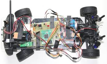
Top view of the car with all the sensors mounted
Encoder wheel and the photo sensor LED
As mention earlier the encoder wheel must me mounted on one of the moving part of the car that we want to measure the velocity. Therefore, as it happen that the designer of the base car did previous thought about and encoder wheel we have to find a suitable position to mount the wheel without damaging the mechanical and the structural integrity of the base car and as for the other component like the GPS, Ultrasonic sensor it was easier since the do not require to be mounted on any moving part of the car as the result we can simply mount them on provided glass like plastic on top of the base car.
However, when it comes to the encoder wheel we’ve had quite a challenge from an early stage of searching for the right place to mount it before even begin to mount it. It’s even got worst after hours of search for the right place since, mounting the wheel require a complete dismount of the car in order to mount the encoder wheel on to the main shaft of the car closed to the rare wheel as showed both on figure 8 and figure 9.
Again this decision presented another challenge forcing to move the main drive batteries to be shifter about 45 degree to the side in order to make room for the base of the photo sensor that goes right on top of the encoder wheel this is shown on figure 8 and figure 9.
Those challenges did not stop there but went further deep in providing a wrong reading on pulse count at the beginning because of a wrong assumption that the shaft rotation is equal to the wheel rotation and a few vibrations which were causing the sensor to read pulse some time even on stationary position. |