Technical overview
The optical shaft encoder uses an infrared light sensor to detect illumination from an infrared LED passing through color code in the circumference of a rotating wheel.

From basic geometry, we know that the circumference of a circle is equal to (pi) times the diameter of the circle.

The distance traveled by a wheel, then, is simply the circumference of the wheel times the number of revolutions the wheel has made.
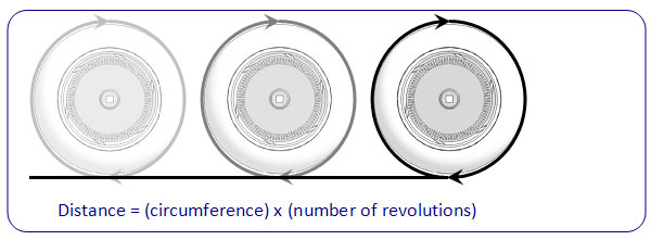
For a standard wheel in the Vex Inventor’s kit, the diameter is 2.75”. So the distance the wheel traveled would be:

By knowing how many slots are cut into the encoder wheel, we can determine how many revolutions the robot wheel has made based on the number of times the light sensor has picked up illumination from the LED. The encoder wheel included in this kit has 300 slots.
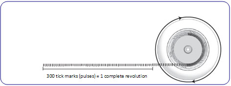
By mounting a shaft encoder on the axle of vehicle wheels axel, we are be able to determine how many times that wheel has rotated. That, in turn, can be used to calculate the distance the car has traveled, based on the diameter of the wheel.
The optical shaft encoder can detect up to 1700 pulses per second, which corresponds to 18.9 revolutions per second and 1133 rpm (revolutions per minute). Faster revolutions will not be interpreted correctly, resulting in erroneous positional data being passed to the microcontroller.
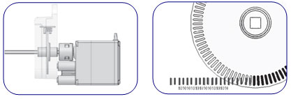
This is a digital sensor, which means that the signal will pass to the ATMega128 microcontroller will either be high (1) or low (0). The sensor output is low (0) when the light from the IR LED passes through the transparent segment of the encoder wheel and high (1) when the light is blocked by an opaque segment of the encoder wheel. This insures the microcontroller to receive a string of 1’s and 0’s as the car moves. The string of 1’s and 0’s will then be interpreted by your program and used to determine the velocity and distance traveled by the car.
Global Positioning System (GPS)
With today’s stand-alone GPS receivers, you are able to pinpoint your own position. But, what’s more useful about stand-alone GPS receivers is that they can transmit your position information to other receivers which in our case the Bluetooth unit via ATMega128 microcontroller.
We decided to use GPS to create a wireless vehicle tracking and control system and plot the exact location of the vehicle on the map using Google® map plug-in on the interface.
To design the Navigation System, we combined the GPS’s ability to pinpoint location along with the ability of plotting the current location on the map. The system include a single stand alone GPS Navigators which transmit all the positioning information to the microcontroller Universal Asynchronous Receiver and Transmitter (UART) port which I would like to call it the control center.
|
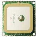
|
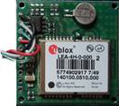
| GPS unit front side |
GPS unit back side |
Let me briefly explain how it works. In order to plot the car position the GPS receives signals from satellites, computes the location information and outputs the data to the ATMega128 microcontroller via a TTL-level asynchronous serial UART interface. With the car location information, the control center display the car positions on an electronic map in order to easily monitor and control the routes. Besides tracking control, the control center can also maintain wireless communication with the GPS units to provide other services such as status control, and system updates.
In-System Programmer
In-System Programming allows programming and reprogramming of any AVR microcontroller positioned inside the end system. Using a simple Three-wire SPI interface, the In-System Programmer communicates serially with the AVR microcontroller, reprogramming all non-volatile memories on the chip.
In-System Programming eliminates the physical removal of chips from the system. This will save time, and money, both during development in the lab, and when updating the software or parameters in the field.
 |
 |
| Atmel® AVRISP MK2 |
Six-wire connection between Programmer and Target System |
MCU Programming
AVRStuido®
As far as Atmel® MCU goes AVR Studio from Atmel Corporation is always the number one pick for so many reasons apart from being free. AVR Studio is a Development Tool for the AT90S Series of AVR microcontroller which enables the user to fully control execution of programs on the AT90S In-Circuit Emulator or on the built-in AVR Instruction Set Simulator. AVR Studio supports source level execution of Assembly programs assembled with the Atmel Corporation's AVR Assembler and C programs compiled with IAR Systems’ ICCA90 C Compiler for the AVR microcontrollers.
WinAVR®
AVR Studio is an extremely powerful tool including assembler, compiler, debugger, programmer, etc. However, Integration of AVR-GCC C compiler to it makes this tool much more powerful and more complete playground for developer. Integration of AVR-GCC is done by plug-in automatically. Therefore, this project used the complete set of AVR Studio with WinAVR as AVR-GCC complier including the AVRLibc library and decided to write the entire program in C language rather than assembly language simply because of the time constraint and simplicity except for the user interface on the host computer described below this section.
Graphical User Interface (GUI)
This project was not aimed for an end user who requires high level user interface. Therefore, Microsoft® HyperTerminal provided more than enough to test the subject. However, I found the use of additional GUI not only attractive but easy to manipulate commands by pressing buttons with the use of regular methods of input without the continuous need of pressing the enter key after each command and the need of memorizing each command.
Even though, there are many different ways and method to build a GUI; I found it easy and fast to use Rapid Application Development (RAD) tool like visual basic in my case and take advantage of MSCOMM class in order to make a serial communicate with any port and more over, employ the use of an even driven approach for time efficiency.
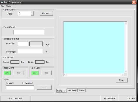
Graphical User Interface of the remote control
|