|
|
Hardware requirements
- Base car with complete wheels
- Pre manufactured regular RC car
- Power supply
- Microcontroller
- Motor
- Main drive motor
- Steering Servo motor
- Speed control Servo motor
- Sensors and reading units
- Global Positioning System (GPS) Unit
- Encoded wheel and light sensor unit
- Collision detector
- Communication (Feedback to PC)
- In-System Programmer (ISP)
|
Software requirements
- Windows® based PC
- Device programming
- IDE: AVR Studio®
- WinAVR®
- Programming language: C
- Graphical User Interface (GUI)
- IDE: Visual Basic 6.0
- Programming: Visual Studio
|
The base of the car
An on shelf car with complete wheels, battery and two servos is used for the entire project to save time in constructing the base of the car.
Obstacle detection is essential to the development of dynamic environmental models for autonomous mobile robots, autonomous guided vehicle, as well as similar user-propelled systems. The pursuit of appropriate sensor technologies has been riddled with issues including cost, accuracy, interference and noise. Many different sensor technologies have been used to develop 2-D environmental models including ultrasonic, laser, and infrared range-finders. Ultrasonic sensors are popular due to their low cost, small size, low power consumption, and relatively simple signal processing requirements, which facilitate operation in real-time. However, ultrasonic range finders have several drawbacks including low angular resolution, slow data collection rate (due to longer time-of- flight), specular reflection, sensitivity to changes in temperature and humidity, and relatively low accuracy in distance measurements compared to their laser counterparts. Yet we have chosen ultrasonic range finder SRF10 for a demonstration purpose.
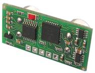
The ultrasonic SRF10 Range finder offers precise ranging information from roughly 0 cm to 2.5 meters.
 
SRF10 Ultrasonic range finder sensor (front and back)
This rage, easy interfacing and minimal power requirements make this an ideal ranger for this project

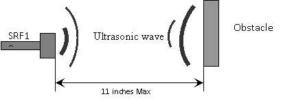
General diagram of range finder sensor
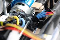
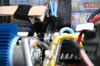
Encoder wheel
Optical shaft encoders are commonly used for position and motion sensing. Basically, a disc with a pattern of cutouts or color-coded around the circumference is positioned between an LED and a light detector; as the disc rotates, the light from the LED is blocked in a regular pattern. This pattern is processed to determine how far the disc has rotated. If the disc is then attached to a wheel on a car, it is possible to determine the distance that wheel traveled, based on the circumference of the wheel and the number of revolutions it made.
 |
 |
| Encoder wheel (angle 1) |
Encoder wheel (angle 2) |
|