Theory and System Description
Global Positioning System (GPS)
The model used on this project is neither the fastest nor the accurate GPS unit on the market however, it’s sufficient enough for an experimental project like this. The unit uses NMEA 0183 as the base protocol for communication.
The National Marine Electronics Association (NMEA) is a non-profit association of manufacturers, distributors, dealers, educational institutions, and others interested in peripheral marine electronics occupations. The NMEA 0183 standard defines an electrical interface and data protocol for communications between marine instrumentation.
All data is transmitted in the form of sentences. Only printable ASCII characters are allowed, plus CR (carriage return) and LF (line feed). Each sentence starts with a "$" sign and ends with <CR><LF> with three basic kinds of sentences: talker sentences, proprietary sentences and query sentences.
NMEA 0183 sentence identifier and formats
GGA Global Positioning System Fix Data. Time, Position and fix related data for a GPS receiver

- Time (UTC)
- Latitude
- N or S (North or South)
- Longitude
- E or W (East or West)
- GPS Quality Indicator,
- - fix not available,
- - GPS fix,
- - Differential GPS fix
- Number of satellites in view, 00 - 12
- Horizontal Dilution of precision
- Antenna Altitude above/below mean-sea-level (geoid)
- Units of antenna altitude, meters
- Geoidal separation, the difference between the WGS-84 earth ellipsoid and mean-sea-level (geoid), "-" means mean-sea-level below ellipsoid
- Units of geoidal separation, meters
- Age of differential GPS data, time in seconds since last SC104 type 1 or 9 update, null field when DGPS is not used
- Differential reference station ID, 0000-1023
- Checksum
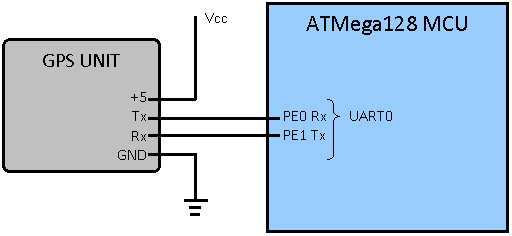
The GPS Tx port is connected to the Rx port on UART0 port of the microcontroller with a board rate of 4800 therefore, the MCU checks if there is any data on the UART0 buffer any time GPS data is required.

GPS to MCU pin connectivity diagram
The Rx pin of the GPS as shown on the figure 15 above is connected to the Tx or PE1 on UART0 of the ATMega128 MC however, this connection was unnecessary for this project since we do not send any kind of data back to the GPS unit.
SRF10 Ultrasonic range finder sensor
Two SRF10 are used on this project in order to detect front and back obstacle by mounting the sensor one on front and one back of the vehicle. The SRF10 uses bi-directional 2 wire bus (I2C) as a protocol to communicate with the MCU.
The I2C was developed by Philips Company back in 1980’s to create a simple inline bus communication as follows: each device on a bus will have a unique identification pre given by the factory with a way to change it later on. Then one device act as a master and the rest as a slave therefore, all the communication will be initiated by the master usually the MCU.
Let demonstrate this by example, assuming that the MCU wants to send data to one of the slave device with i2C protocol.
First the MCU issue a START condition which will put all the slave devices to listening mode waiting for incoming signal from the master. Then, afterward the MCU will send a particular address of the target device along with the access mode (READ/WRITE) of operation. Having received the address, each slave devices will compare the received address with their own address. Then, Target device will send an acknowledgment signal and the rest will wait until the bus is released by the STOP signal again before doing anything else.
Once the MCU receives the acknowledgment, it can start transmitting or receiving data before issuing the STOP condition allowing access of the bus for the rest to use.
Light Emitting Diode (LED)
Two regular LED’s are used on the car to simply emulate the front and the back light a normal vehicle. Each LED are connected the particular data port on the microcontroller which are then assigned HIGH and LOW bit in order to power the LED ON and OFF after in initializing those pin for output.
Photo sensor and Encoder wheel
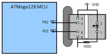
GP1A038RBK photo sensor by Sharp® and a regular color encoded wheel is used on this project for the velocity and distance coverage measurements exactly as describe above.

Encoder sensor to MCU pin connectivity diagram
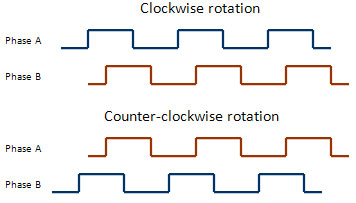
However, some facts are worth mentioning about encoder wheel and the sensor. The sensor output a square wave signal each time the light is blocked by the opaque color code “black” and each time the light pass through the transparent section of the encoded wheel.

Squarer wave signal of the encoder sensor
In order to apply the above mentioned calculation for the velocity and the distance traveled by the car we have to first find a way to count each click/pulse or simply one square of each phase.
Generally there are two different ways of reading a value out of a sensor depending on the underlining microcontroller.
- Hardware Pooling and
- Hardware Interrupt
Hardware Pooling
Hardware pooling is a method used occasionally in a single thread application by manually checking a value of a device on a particular pin now and then. This method may seem easy and straight forward for lot of people. However, I found it not a good method for this project since I will need to transfer control over to some routine for further process on the data that I read and once you pass the program control to a different function we might miss the pulse without check it. Therefore, I found the second method suitable.
Hardware Interrupt
An interrupt is a hardware/software device which causes a software function to occur when something happens in the hardware. Specifically, whenever the detector A pulse goes high, the MCU can be interrupted such that it suspends its ongoing task and runs a special software routine (called an interrupt handler) which will then increment the pulse count for the computation of the velocity and distance traveled.
Bluetooth (BT)
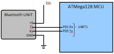
The Bluetooth device on the other hand is simply used to provide communication with the remote host (computer). The BT has the receiver (Rx) and the transmitter (Tx) port apart from the power and the ground connector. Since ATMega128 is equipped with two UART port, the second (UART1) is used by the BT but unlike the GPS on UART0 the BT requires a faster board rate 9600 and unlike GPS this time we need both Rx and Tx from the BT therefore, the Tx /Rx of the Bluetooth goes to the Rx/Tx of the MCU on the UART1 respectively.
Note we have to make sure when connecting the car with the remote host a correct board rate must be used to guarantee a proper communication between the two parties.

Bluetooth sensor to MCU pin connectivity diagram
Servo Motors
The car is equipped with two servos in order to steer the car left to right and vice versa; to accelerate/decelerate and finally to reverse the car backward.
Each servo consists of a dc motor, gear train, potentiometer, and some control circuitry all mounted compactly in a case. The steering servo control signal pin is connected to MCU pin PB0 and the speed control servo to PB2 pin. Therefore, but varying the value of those two pins we can steer, start, stop, and reverse the car with the help of the main motor on board of the car for driving the car.
In-System Programmer (ISP) for Atmel's AVR® ATMega128 MCU
There is neither short cut nor any other way to move our compiled code in to an actual MCU. Therefore, the question rely is affordability, compatibility and so on.
The AVRISP MK2 is pick for this project not only because its compact and easy-to-use In-System Programming tool for developing applications with Atmel's AVR microcontrollers but, it is also an excellent tool for field upgrades of existing applications on any compatible AVR microcontrollers.
The AVRISP MK2 Programming interface is integrated in AVR Studio and all the Flash, EEPROM and all Fuse and Lock Bit options. ISP programmable can be programmed individually or with the sequential automatic programming option.
AVR Programming
Eventually, in this project AVRStudio® Integrated Development Environment (IDE) by Atmel in combination with WinAVR is used containing AVRLibc C library for fast development.
The AVRLibc package provides a subset of the standard C library for Atmel AVR 8-bit RISC microcontrollers. In addition, the library provides the basic startup code needed by most applications.
Apart from some section of the code, most components where programmed using the help of the AVRLibc library in order to avoid rewriting the existing and reusing an already tested function. This does not only shorten life of the programming time but it also help in letting us focus on the connection and configuration of the device in case of any unexpected output from the device.
|